• Home
  • Services
  • Request A Quote
Mid Ohio Mobile Mechanic Logo
  • About Us
  • Schedule Appointment
  • Contact
Mid Ohio Mobile Mechanic Logo
  • Home
  • Services
  • About Us
  • Request A Quote
  • Schedule Appointment
  • Contact
  • Blog

2013 Ford Fusion Fuse Diagram

/ 24

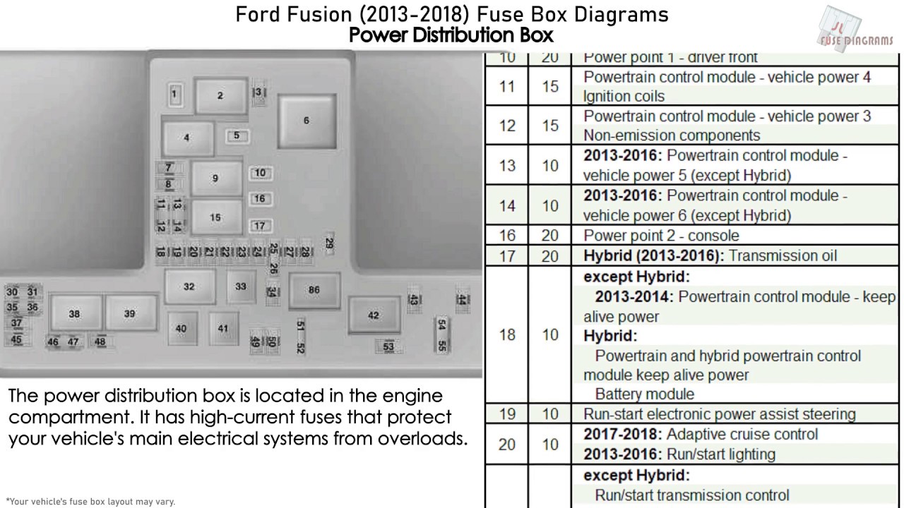
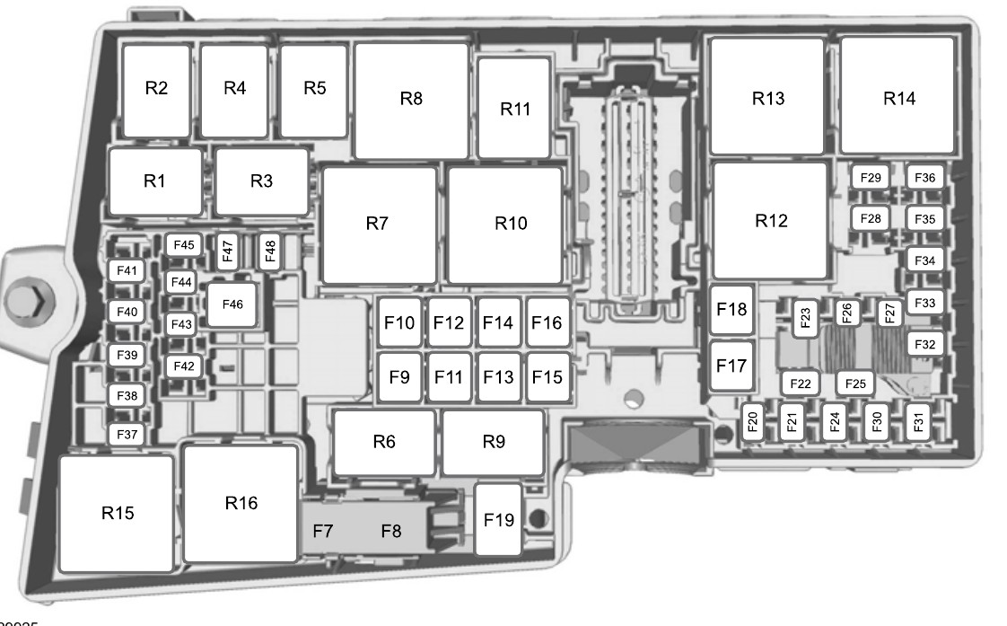
2013 Ford Fusion Fuse Diagram 2013 Ford Fusion Fuse Diagram for battery junction box, body control module and high current junction box 2013 Ford Fusion Fuse Diagram for Battery Junction Box F1 25 Windshield wiper motor, right front F3 15 Rain sensor module F5 20 Rear passenger power outlet socket F7 20 Powertrain Control Module (PCM) F8 20 Mass Airflow / Intake Air Temperature (MAF/IAT) sensor, EVAP purge valve, EVAP canister vent valve, Evaporative Emission (EVAP) purge valve Variable Camshaft liming 12 (VCT12) solenoid, Variable Camshaft Timing 11 (VCT11) solenoid, … Read More

The post 2013 Ford Fusion Fuse Diagram appeared first on Ricks Free Auto Repair Advice.

Please follow and like us:
fb-share-icon
Tweet
Pin Share
Tags: Auto Mechanic, Auto Repair, Mid Ohio Mobile Mechanic
Share Post

Related posts

Read more

2018 Fusion Fuse Diagram

/ 23
2018 Fusion Fuse Diagram 2018 Fusion fuse diagram for two fuse boxes, one under the hood and one under the dash. The underhood fuse box Continue reading
Read more

2018 F150 Fuse Diagram

/ 47
2018 F150 Fuse Diagram 2018 F150 Fuse Diagram for two fuse boxes; the battery junction box and the body control module 2018 F150 Fuse Diagram Continue reading
Read more

2017 F-150 Fuse Diagram

/ 32
2017 F-150 Fuse Diagram 2017 F-150 fuse diagram for two fuse boxes, one under the hood called the battery junction box and one under the Continue reading
Read more

2018 Explorer Fuse Diagram

/ 28
2018 Explorer Fuse Diagram 2018 Explorer Fuse Diagram for two fuse boxes, one under the hood called the battery junction box (BJB) and the body Continue reading
Read more

2017 Ford Focus Fuse Box Fuse Diagrams

/ 28
2017 Ford Focus Fuse Box Fuse Diagrams 2017 Ford Focus Fuse Diagram for Battery Junction Box F7 40A Anti-lock Braking System pump. Traction control valve. Continue reading

Comments are closed

Please follow & like us :)

Facebook
Facebook
fb-share-icon
Twitter
Visit Us
Follow Me
Tweet
Pinterest
Pinterest
Pin Share
LinkedIn
Share
Privacy Policy.
Terms of Use.
Facebook
Facebook
fb-share-icon
Twitter
Visit Us
Follow Me
Tweet
Pinterest
Pinterest
Pin Share
LinkedIn
Share

CONTACT INFO

(614) 414-2241
Contact@midohiomobilemechanic.com
Columbus, OH 43213

©2025 by Mid Ohio Mobile Mechanic

Home
Request Mechanic
Services
More
More
  • Home
  • About Us
  • Request A Quote
  • Schedule Appointment
  • Contact
  • Blog